projects / 12
Portable PCB Tester Tool
A rugged, handheld diagnostic and firmware flashing tool built for field engineers and warehouse technicians. Packages a Raspberry Pi 5, touch display, battery power management, and custom breakout harnesses into a compact, impact-resistant 3D-printed enclosure.
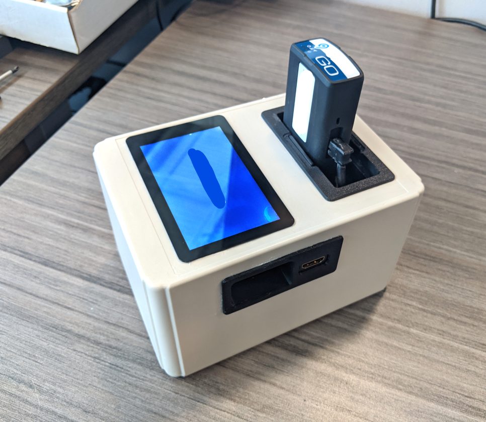
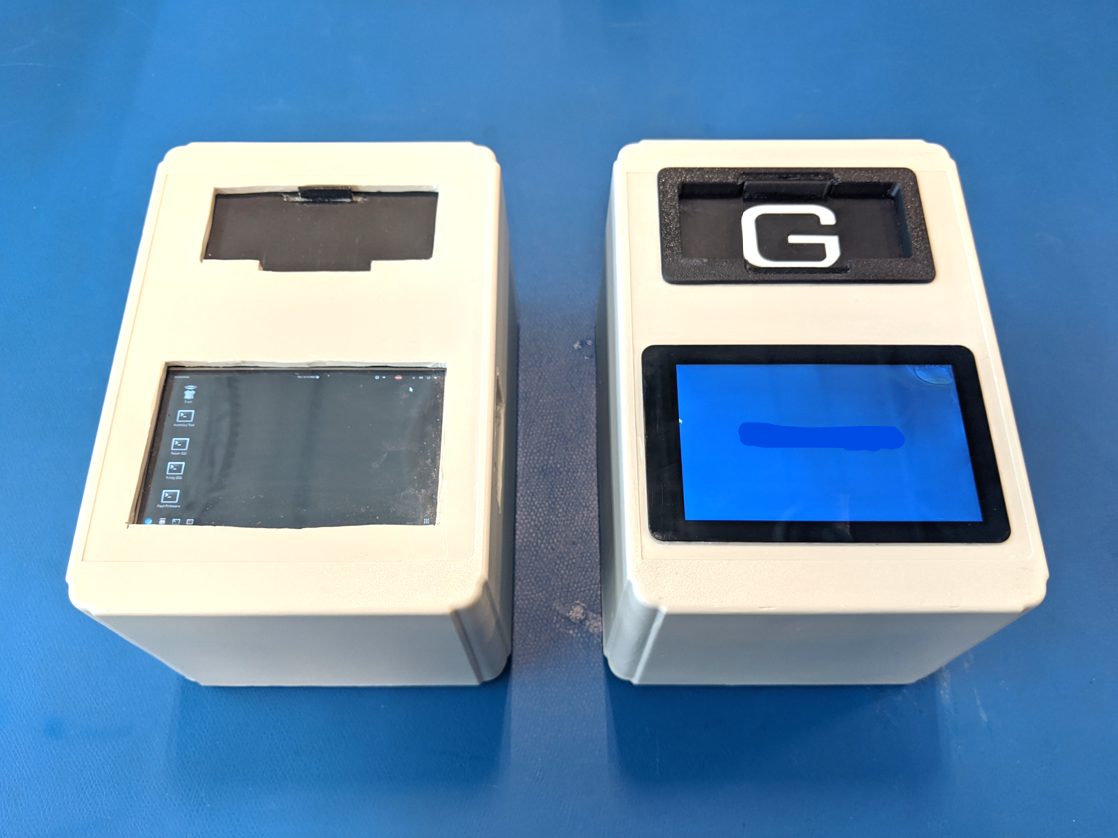
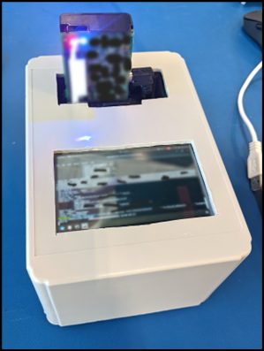
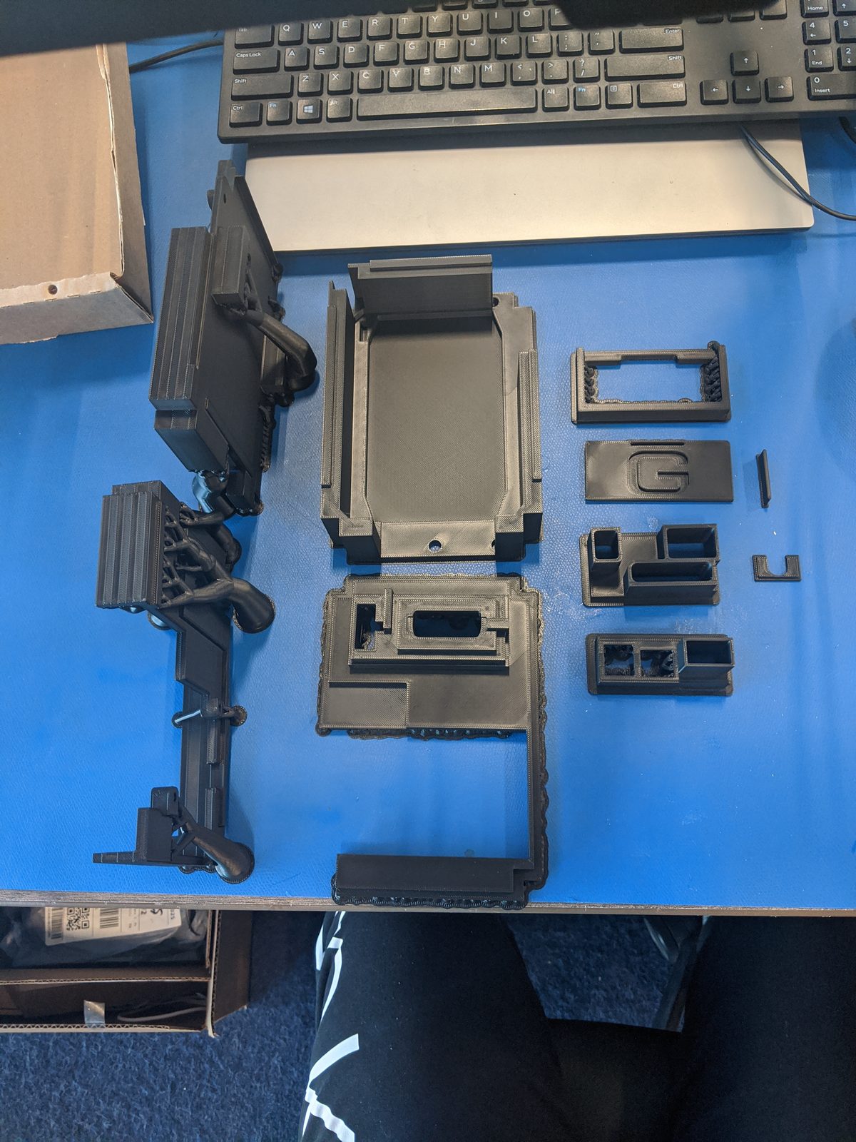
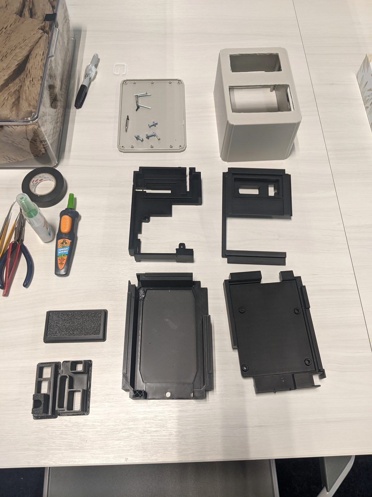
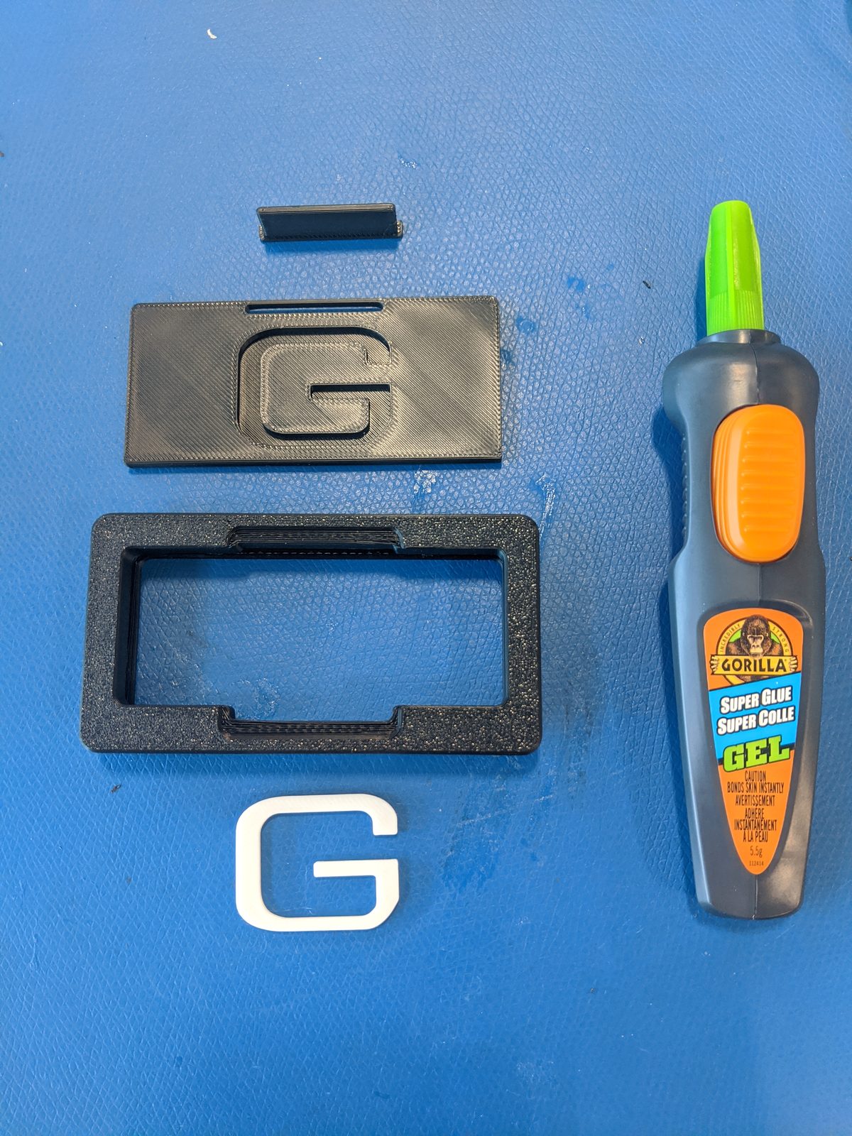
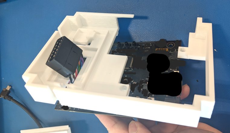
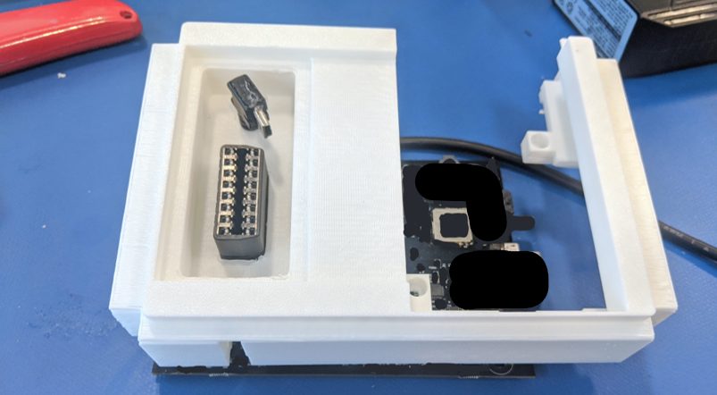
- Designed a multi-layer modular enclosure in CAD with internal thermal ventilation, recessed port protection, and battery isolation.
- Built an integrated power system with battery state-of-charge LED indicators, USB-C PD charging, and hot-swap capabilities.
- Streamlined firmware flashing workflows from 15 minutes down to under 45 seconds with one-touch automated Python scripts.
01Mechanical Design & CAD Assembly
Comprehensive SolidWorks 3D CAD modeling, multi-body kinematics, tolerance stack-up analysis, and assembly architecture.
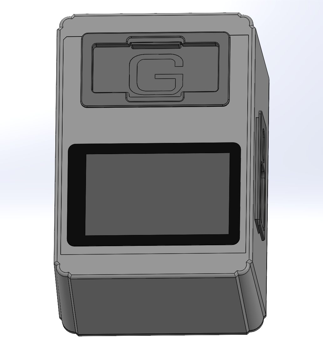
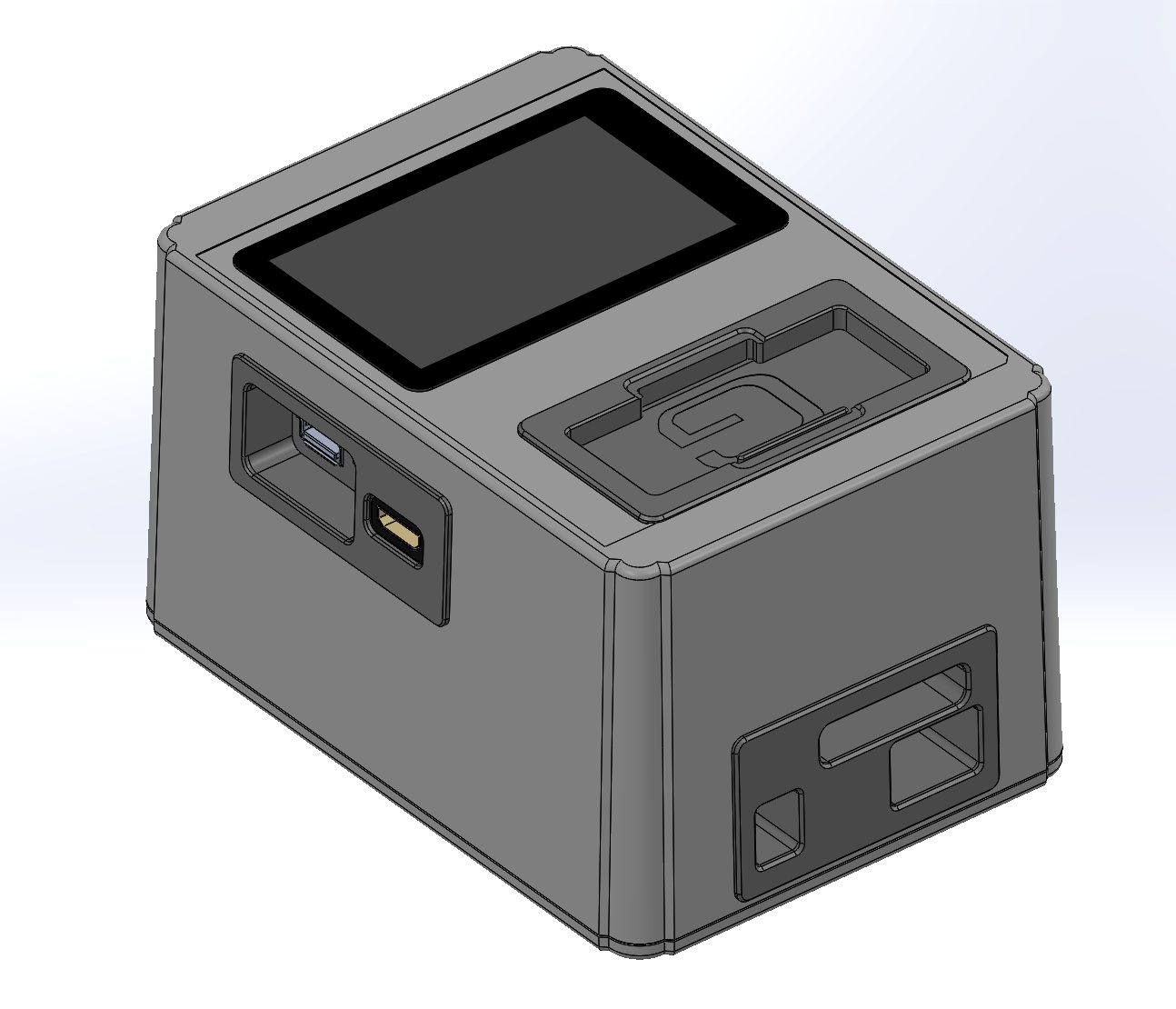
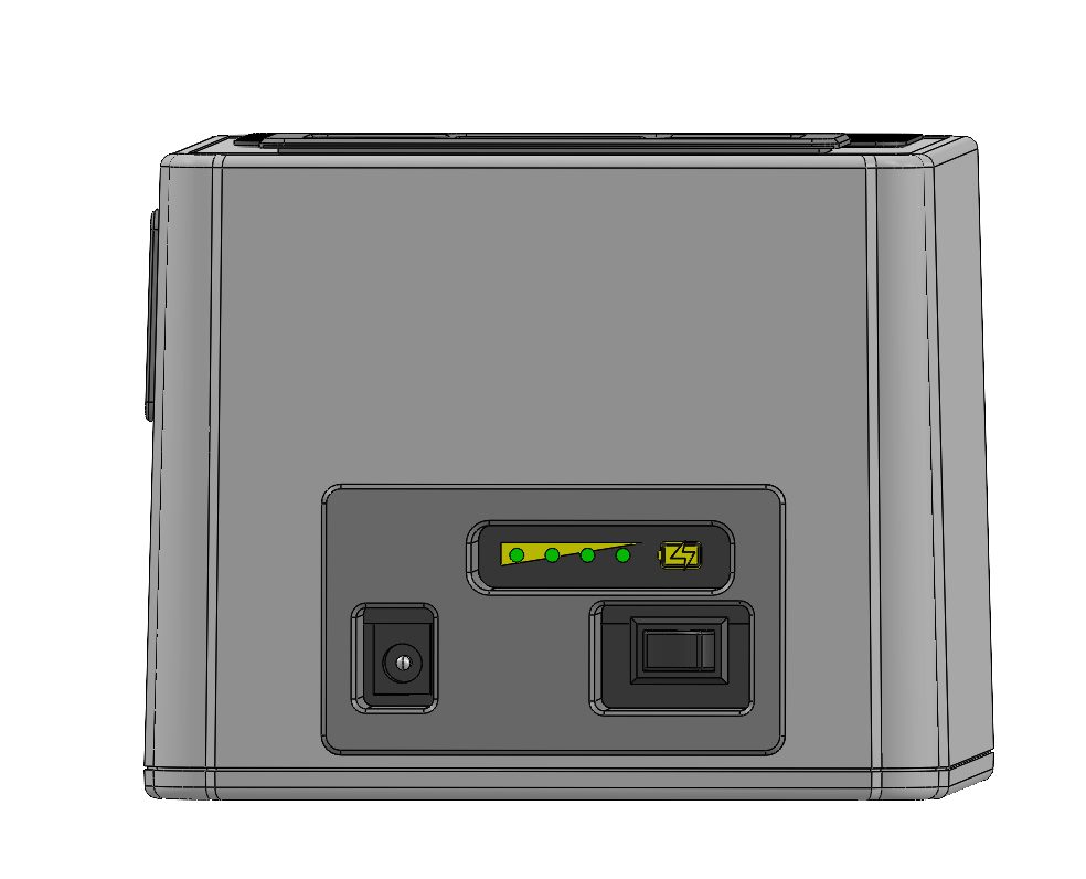
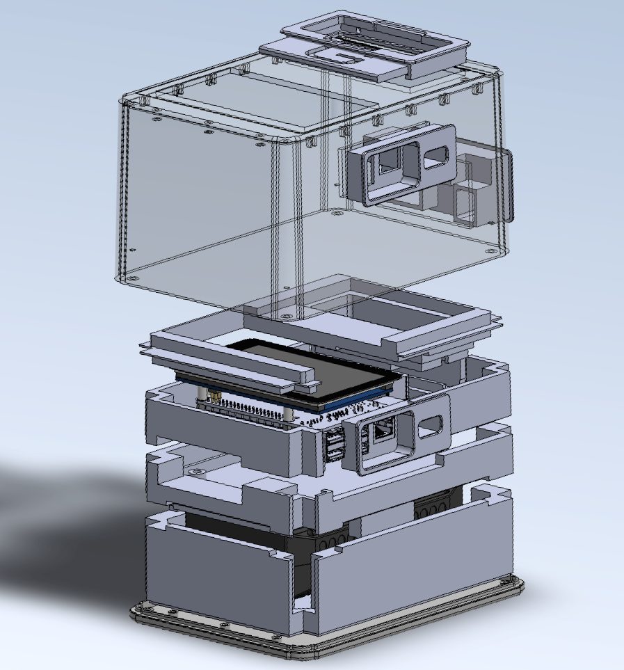
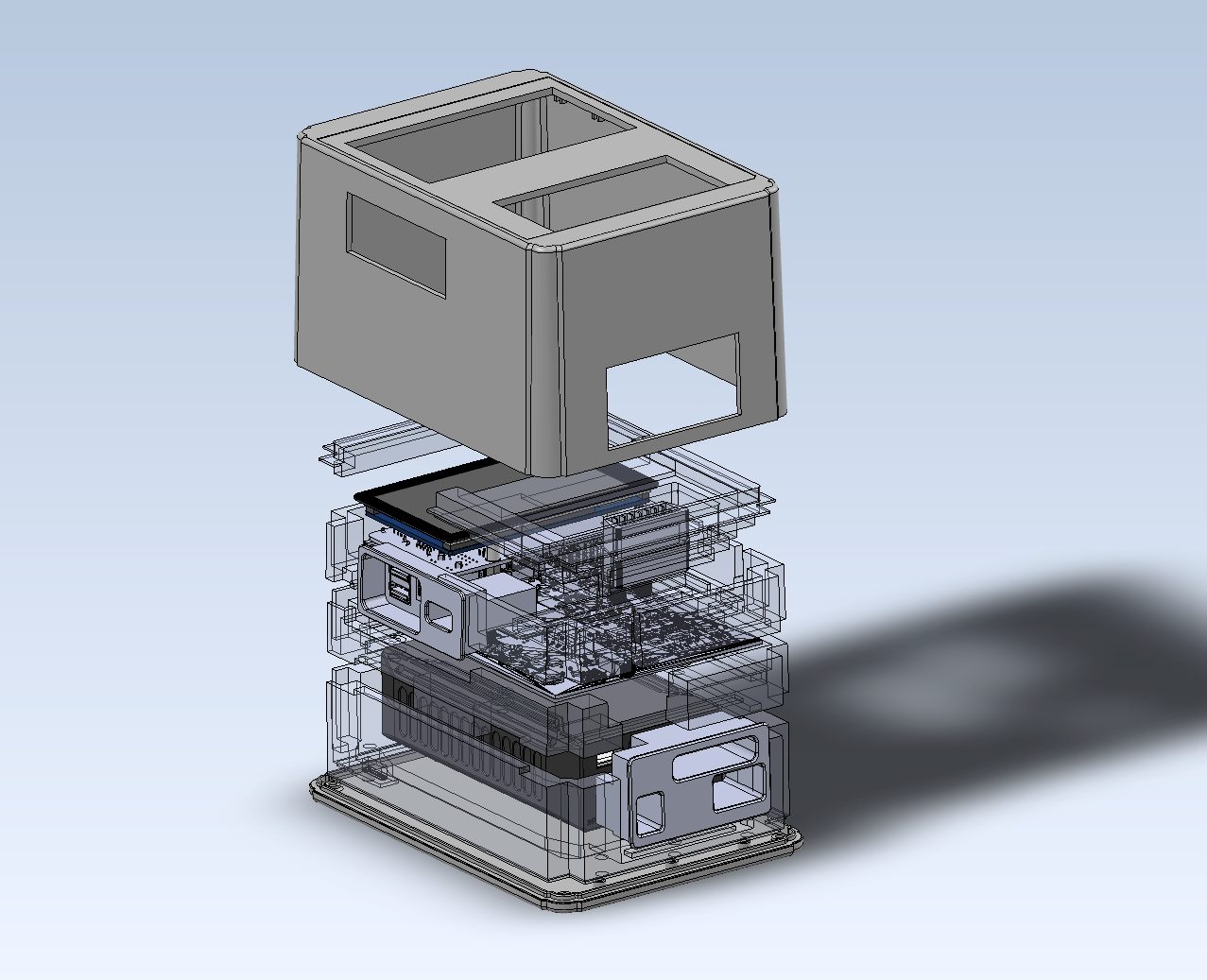
01.1 Handheld Field Tester Architecture & Ergonomic CAD
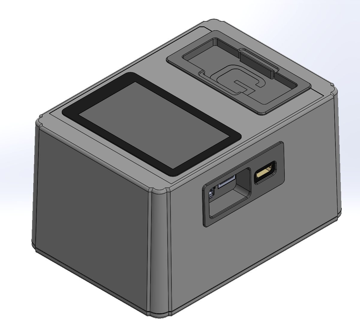
Compact, rugged handheld diagnostic tool CAD assembly designed for single-operator field testing of automated sorting equipment.
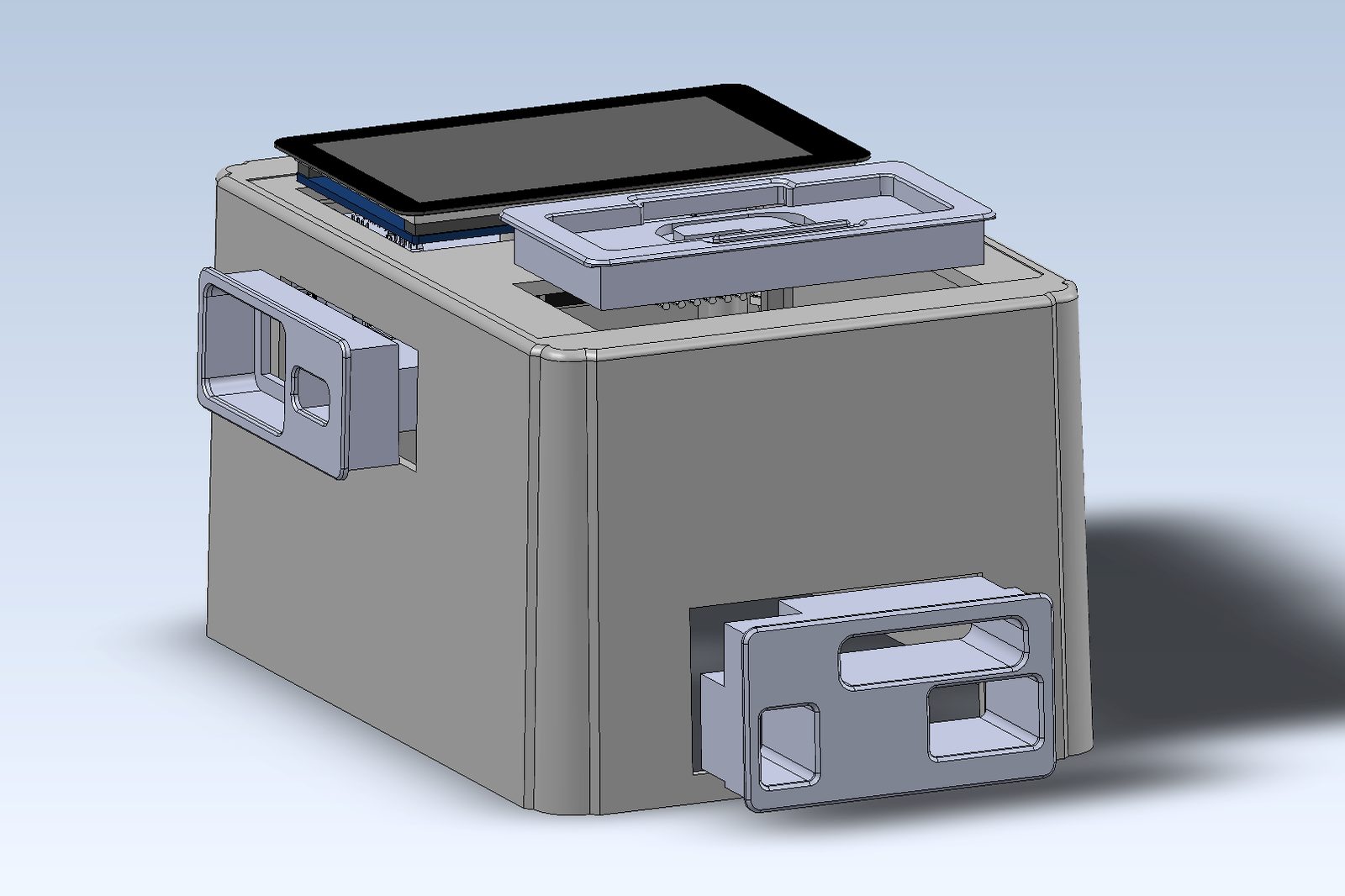
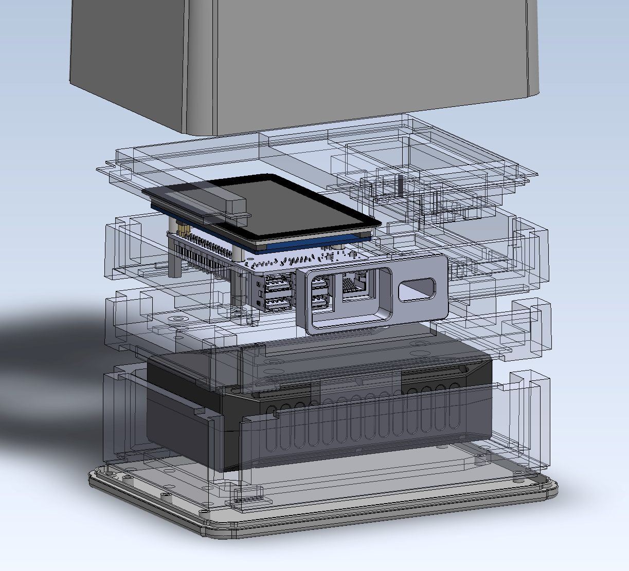
01.2 Modular Sliding Port Covers & Dust Seals
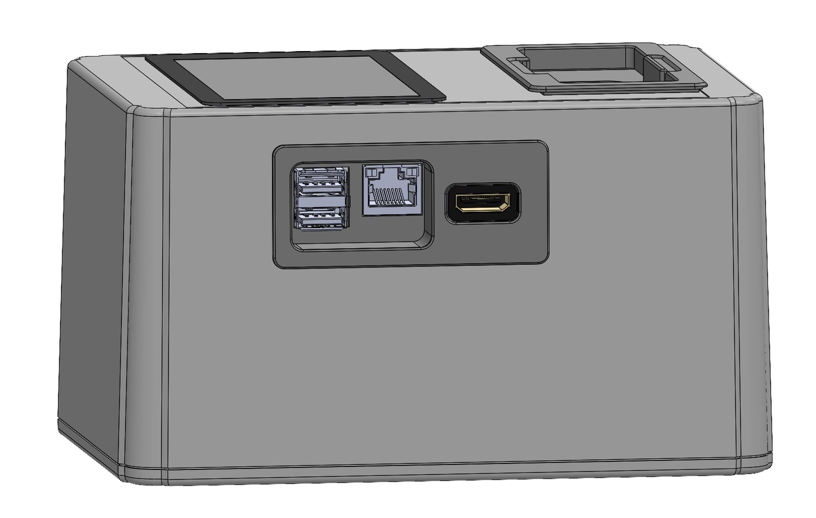
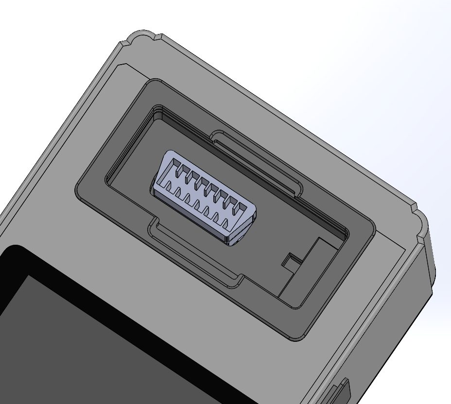
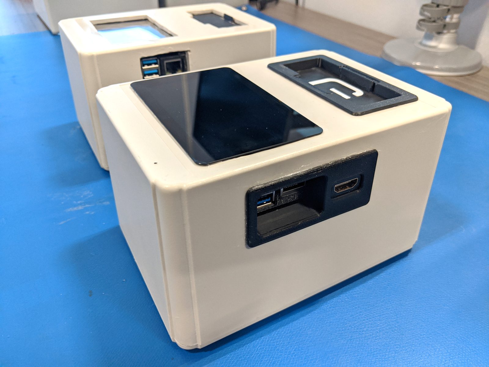
Sliding dust covers and flush-mount bezels protecting Raspberry Pi 5 USB ports, HDMI debug outputs, battery charging, and wire harness connectors.
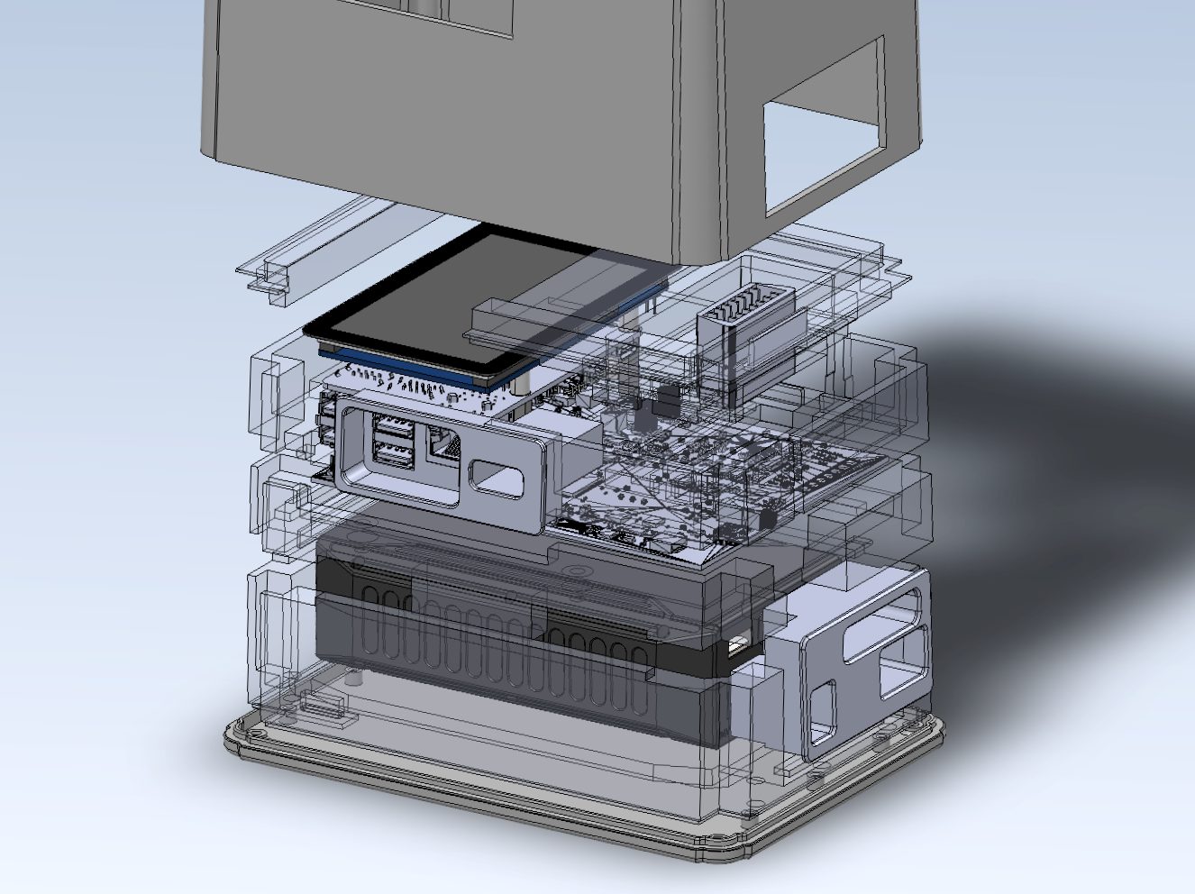
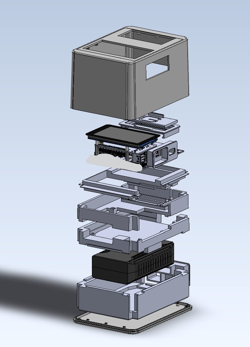
01.3 Stacked Multi-Layer Packaging & Electronics Bays
Four-tier modular internal skeleton separating touchscreen display, Raspberry Pi compute board, test interface PCB, and battery power supply.
02Prototyping, 3D Printing & Fabrication
Rapid prototyping iterations, slicing optimization (Bambu Studio / PrusaSlicer), material selection (PLA / PETG / Carbon Fiber), and precision fit checks.
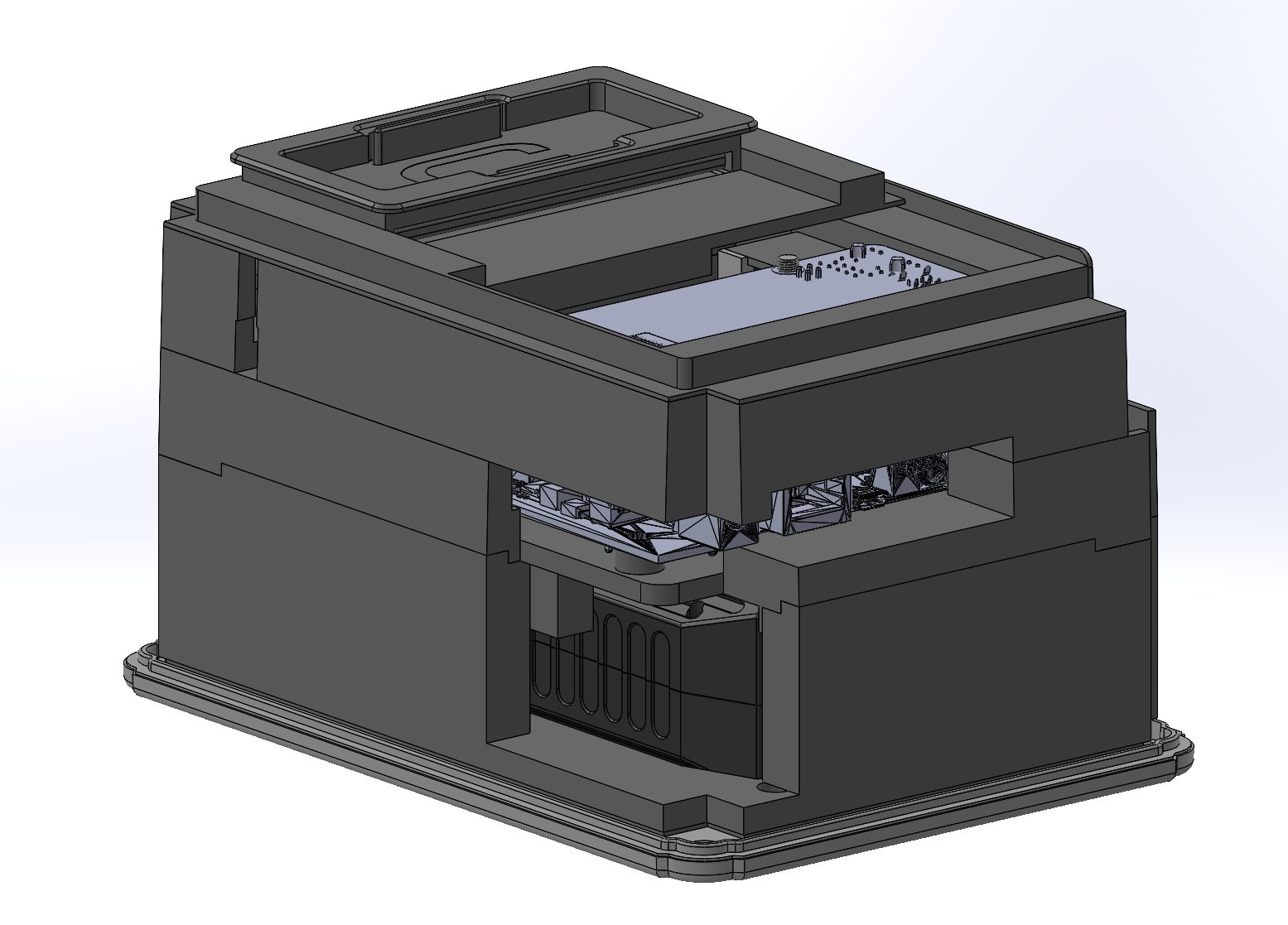
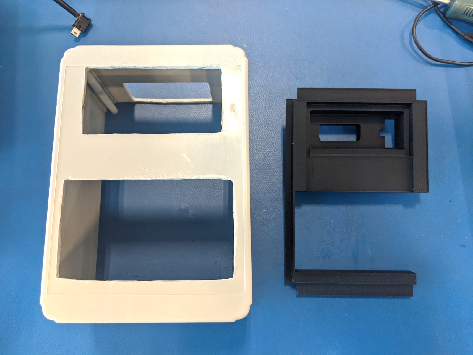
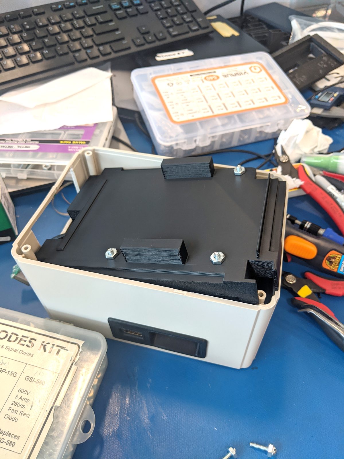
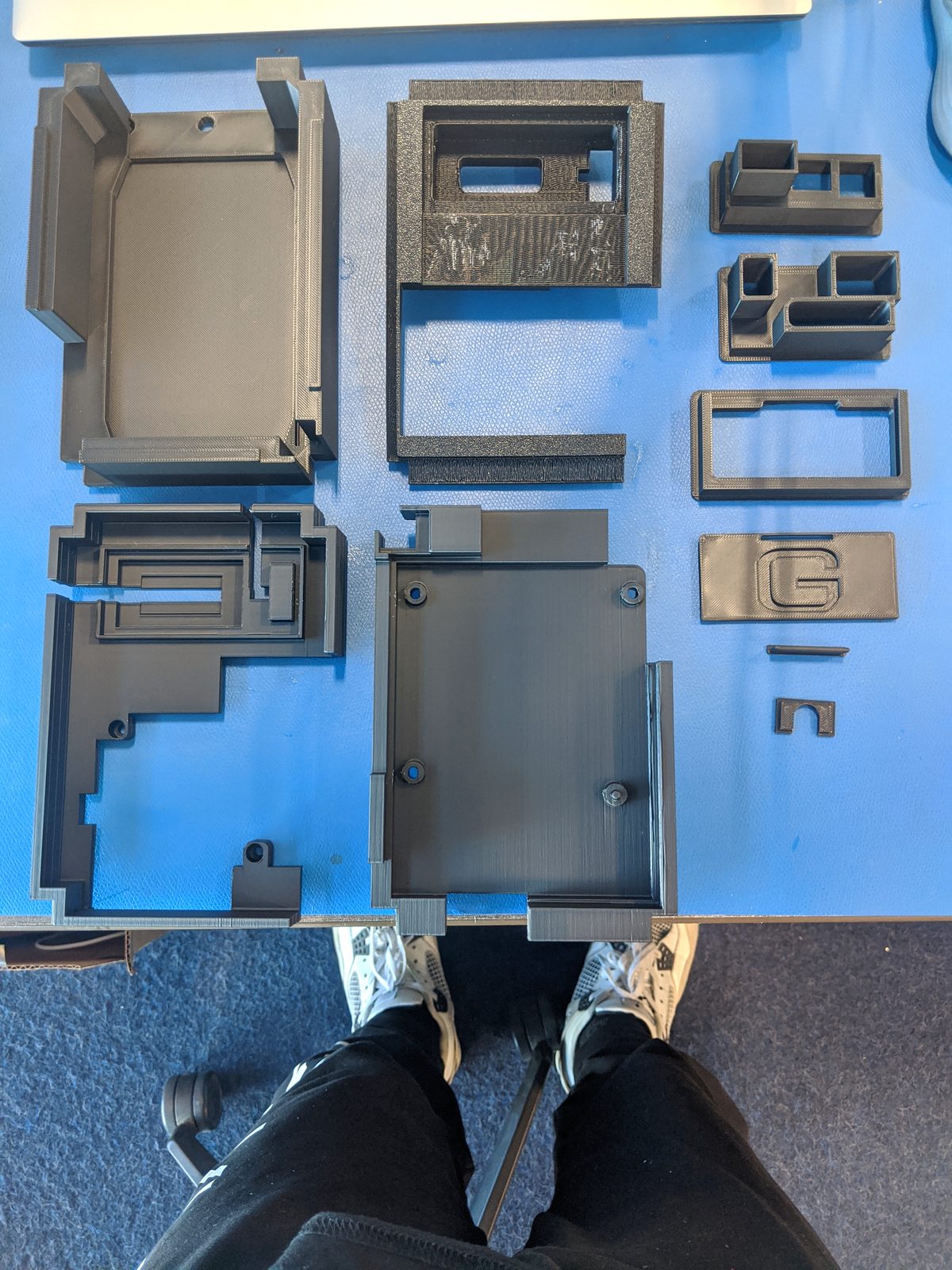
02.1 Multi-Layer Internal Frame Prototyping
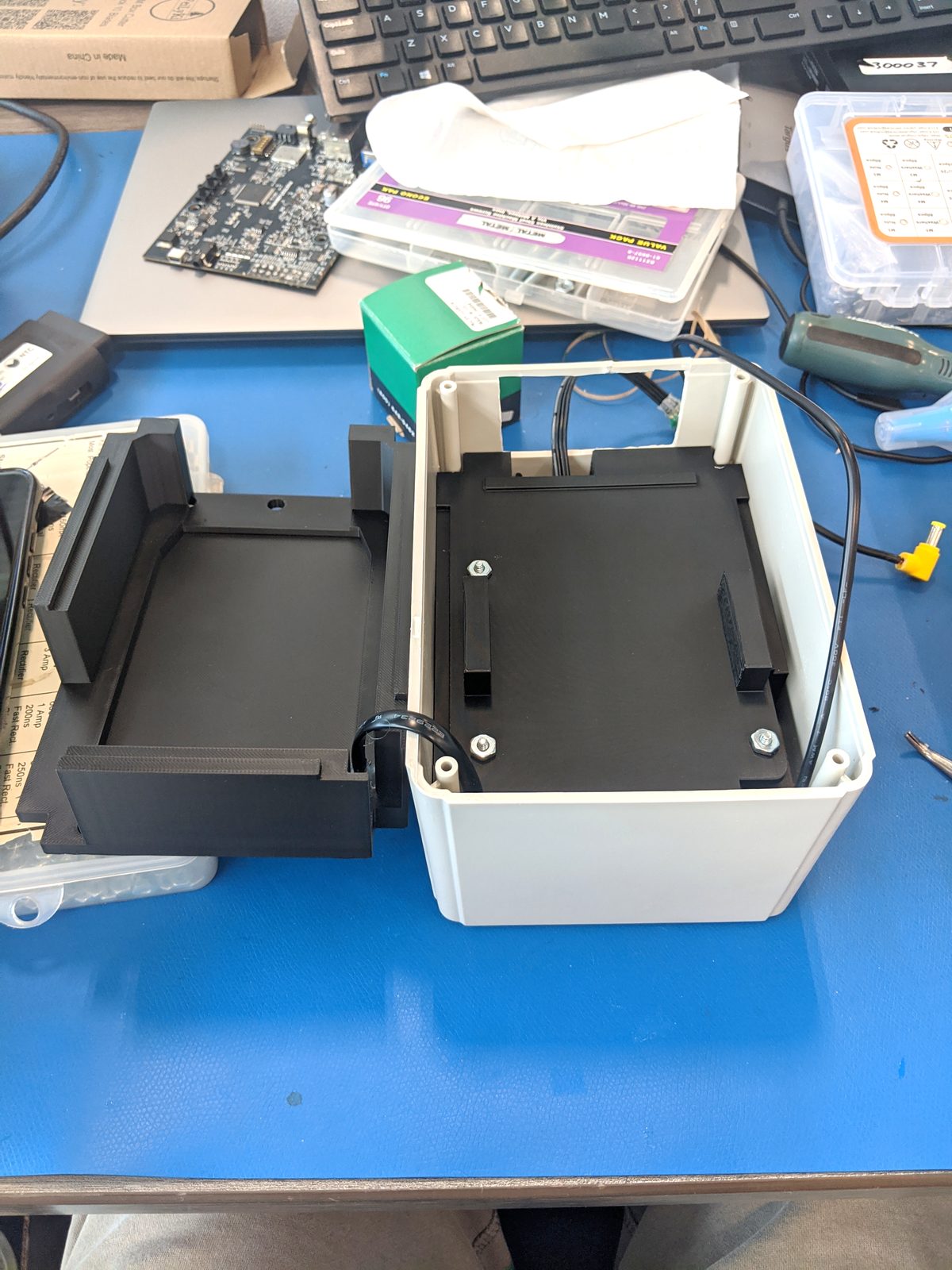
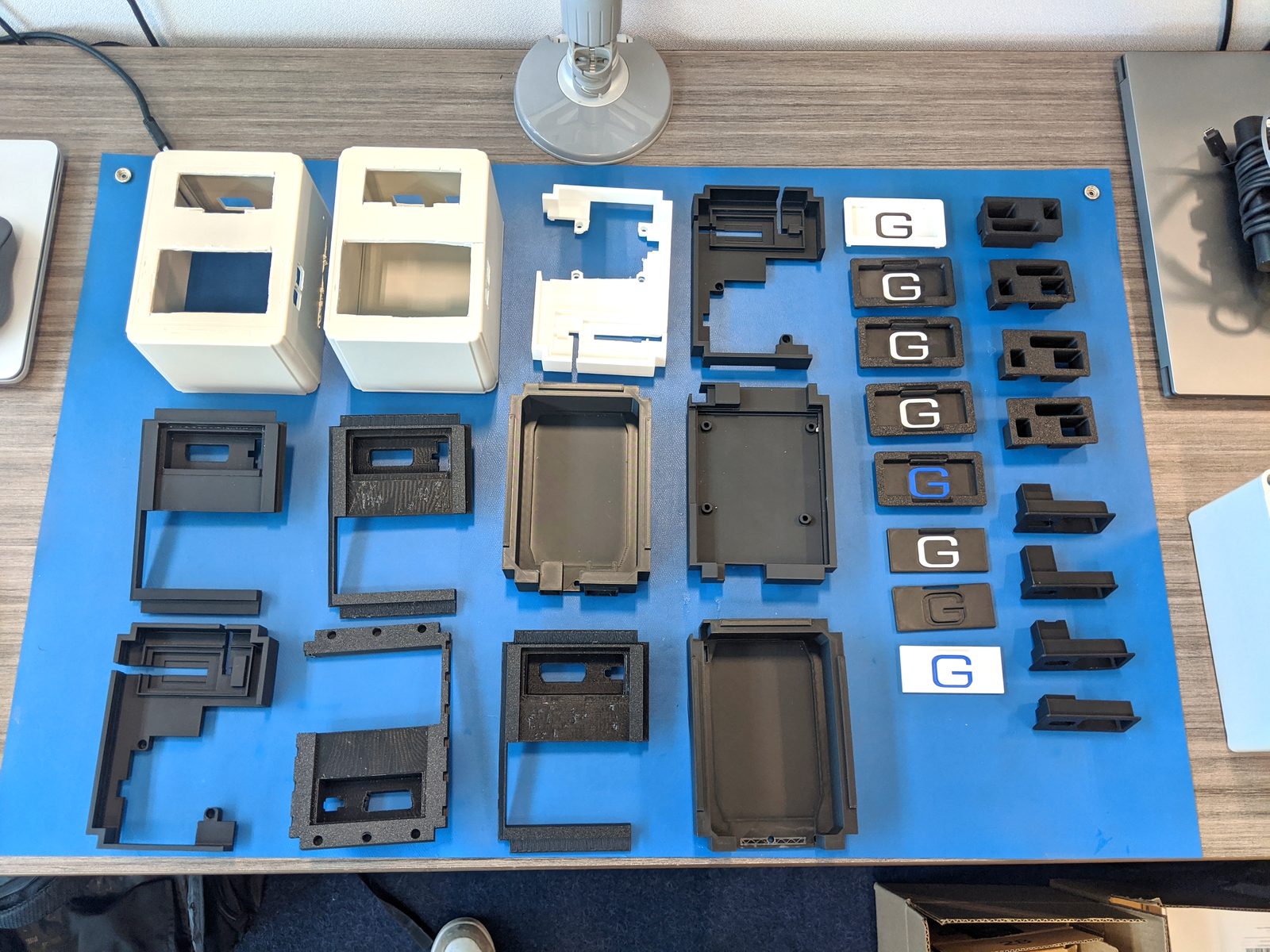
Additive manufacturing of stacked intermediate frames to evaluate tolerance stack-up and verify rigid screw anchor points.
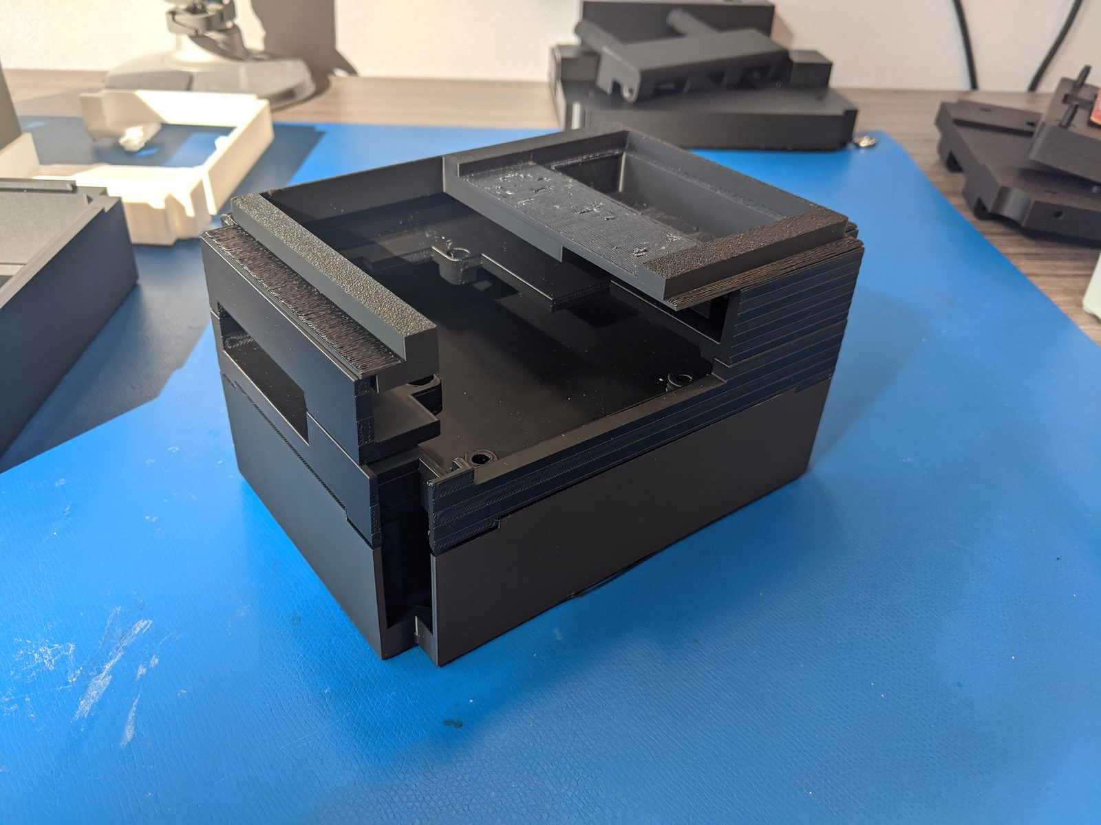
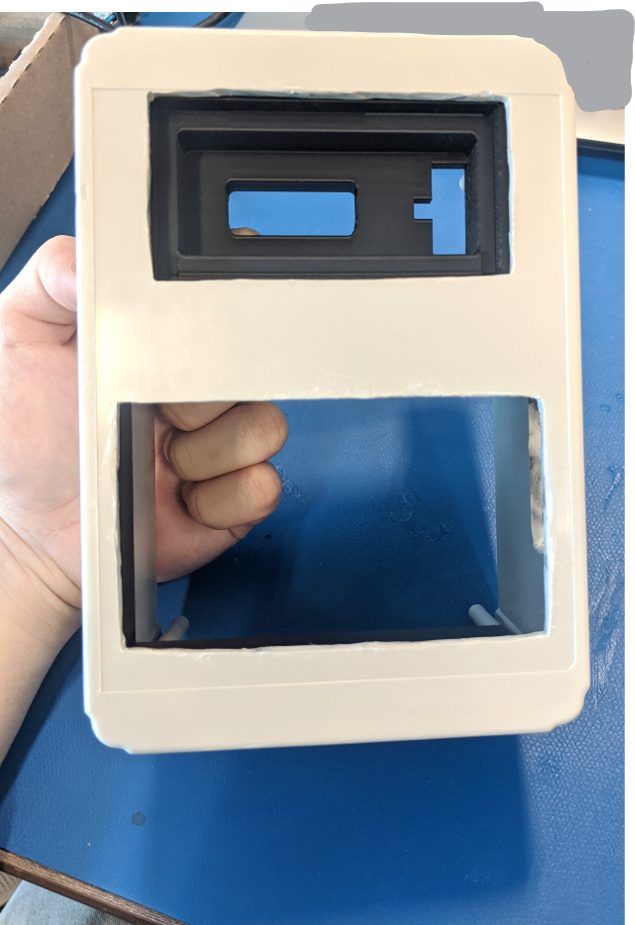
02.2 Custom Sliding Port Covers & ABS Enclosure Fit
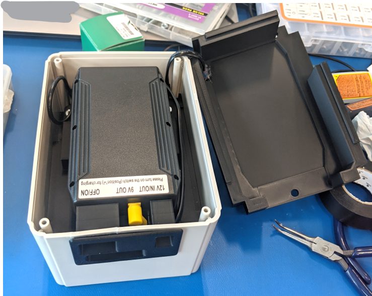
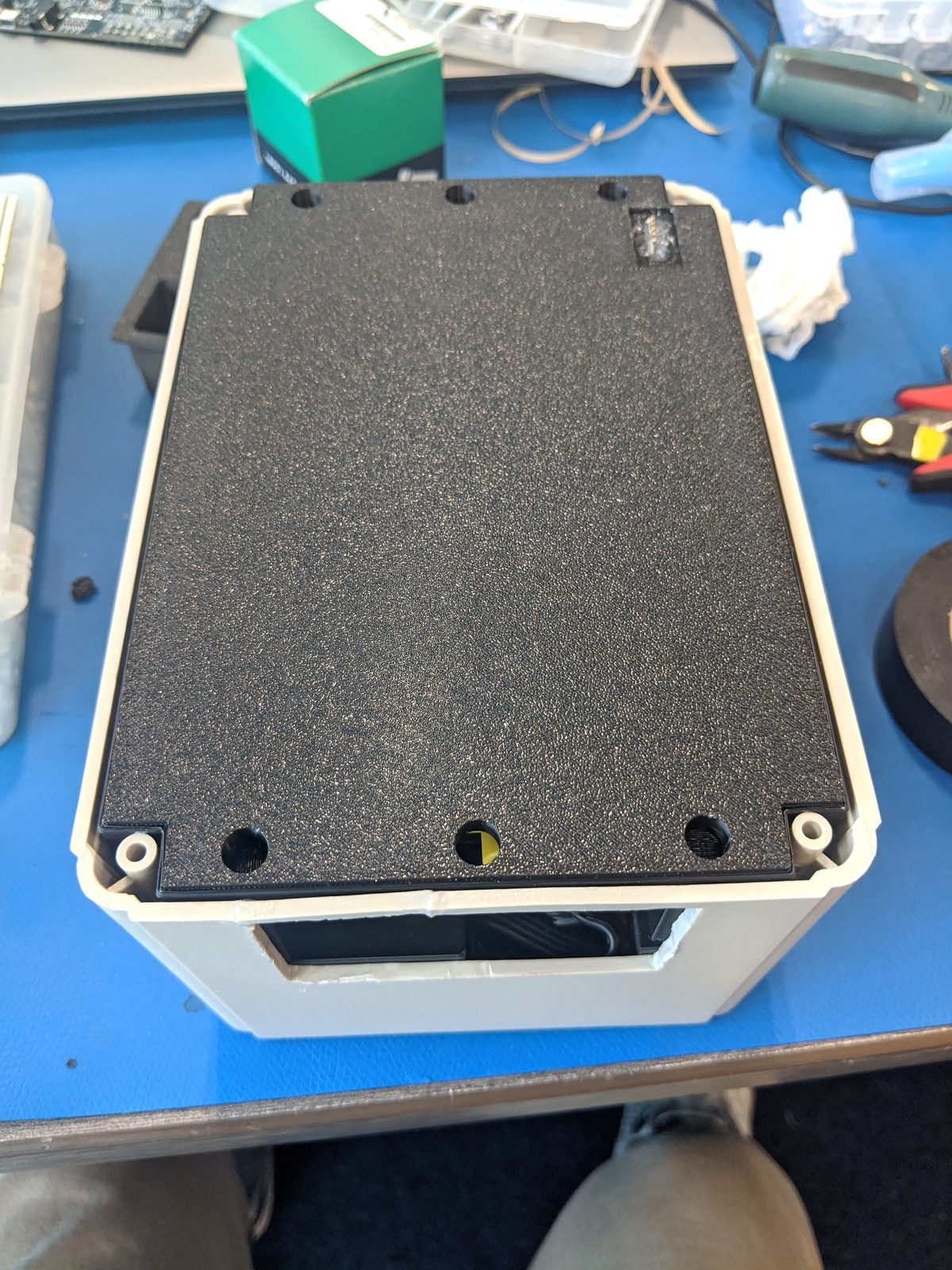
Prototyping sliding cover tracks and test-fitting stacked printed frames within the outer ABS protective shell.
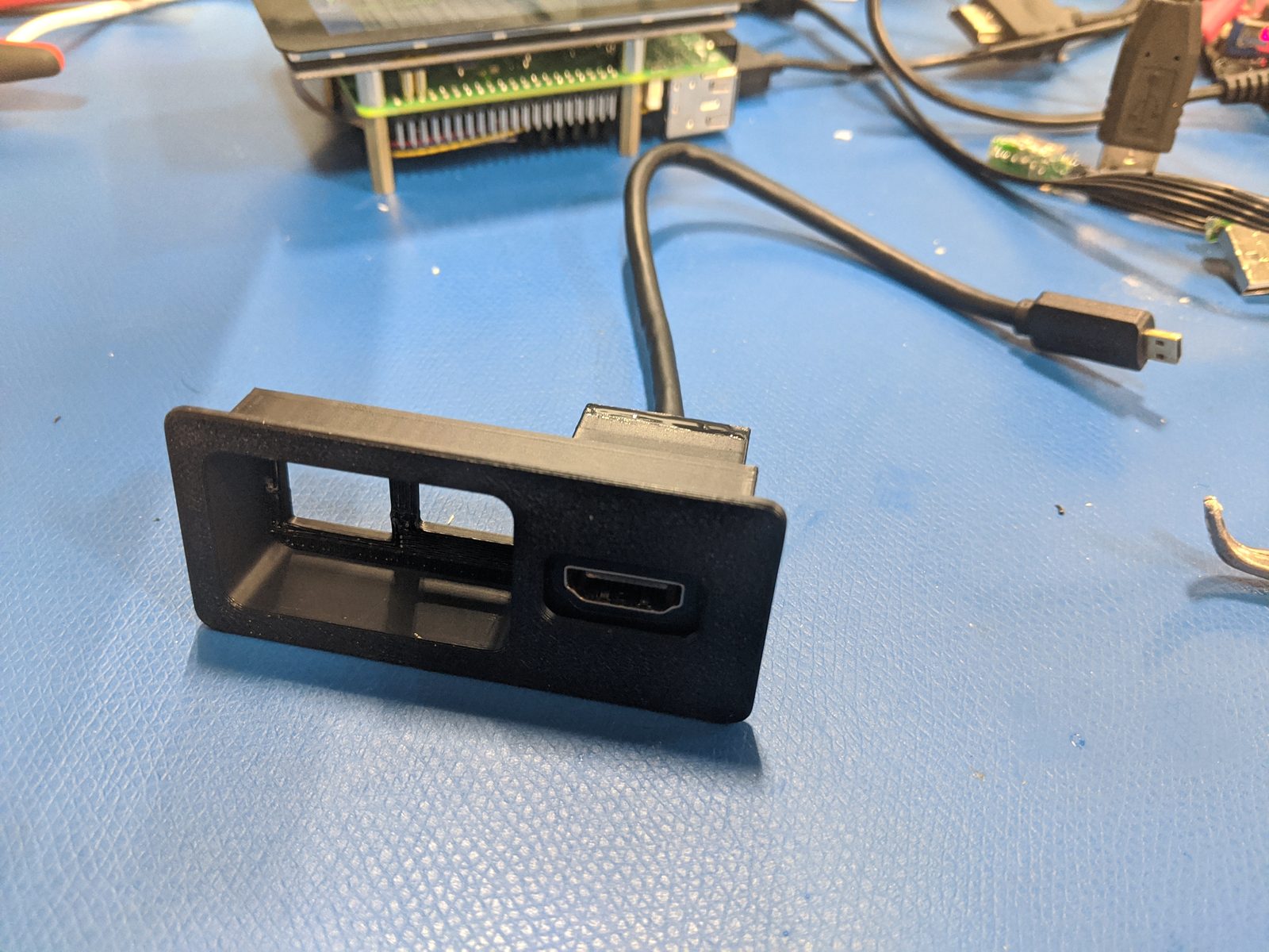
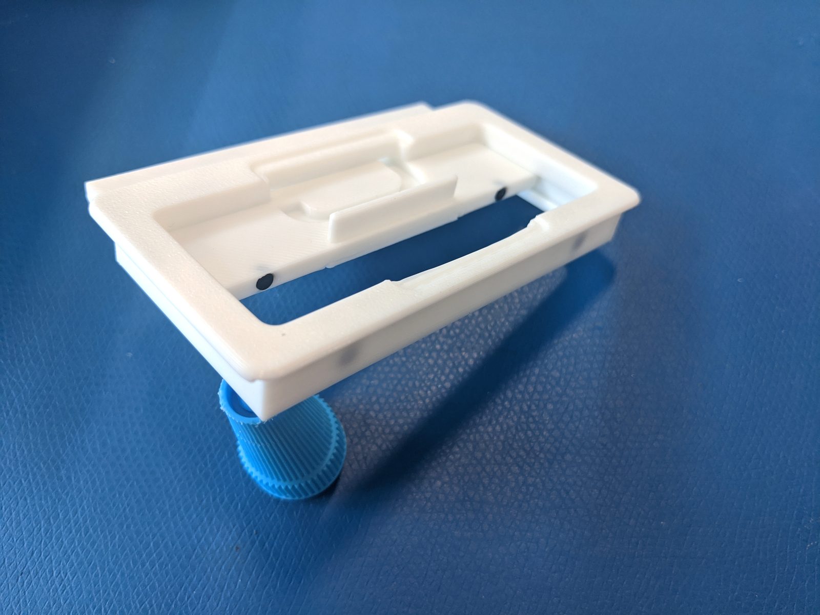
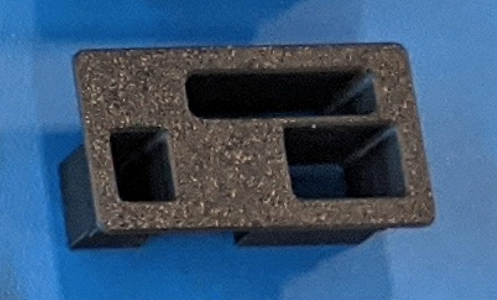
02.3 Internal Cable Channeling & Component Trays
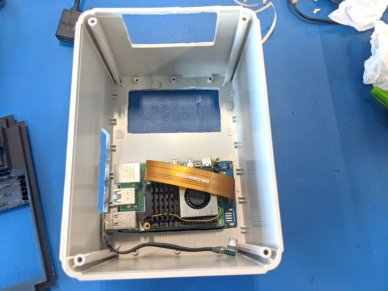
Benchtop test routing of flat flex ribbons, power cables, and test signals through dedicated isolation channels in the sub-chassis.
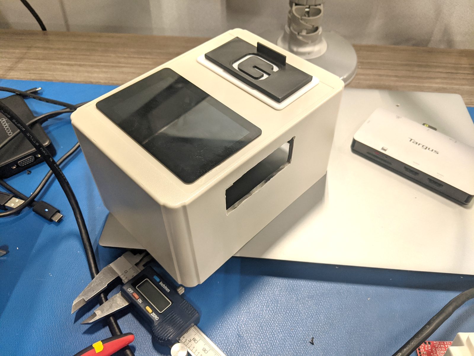
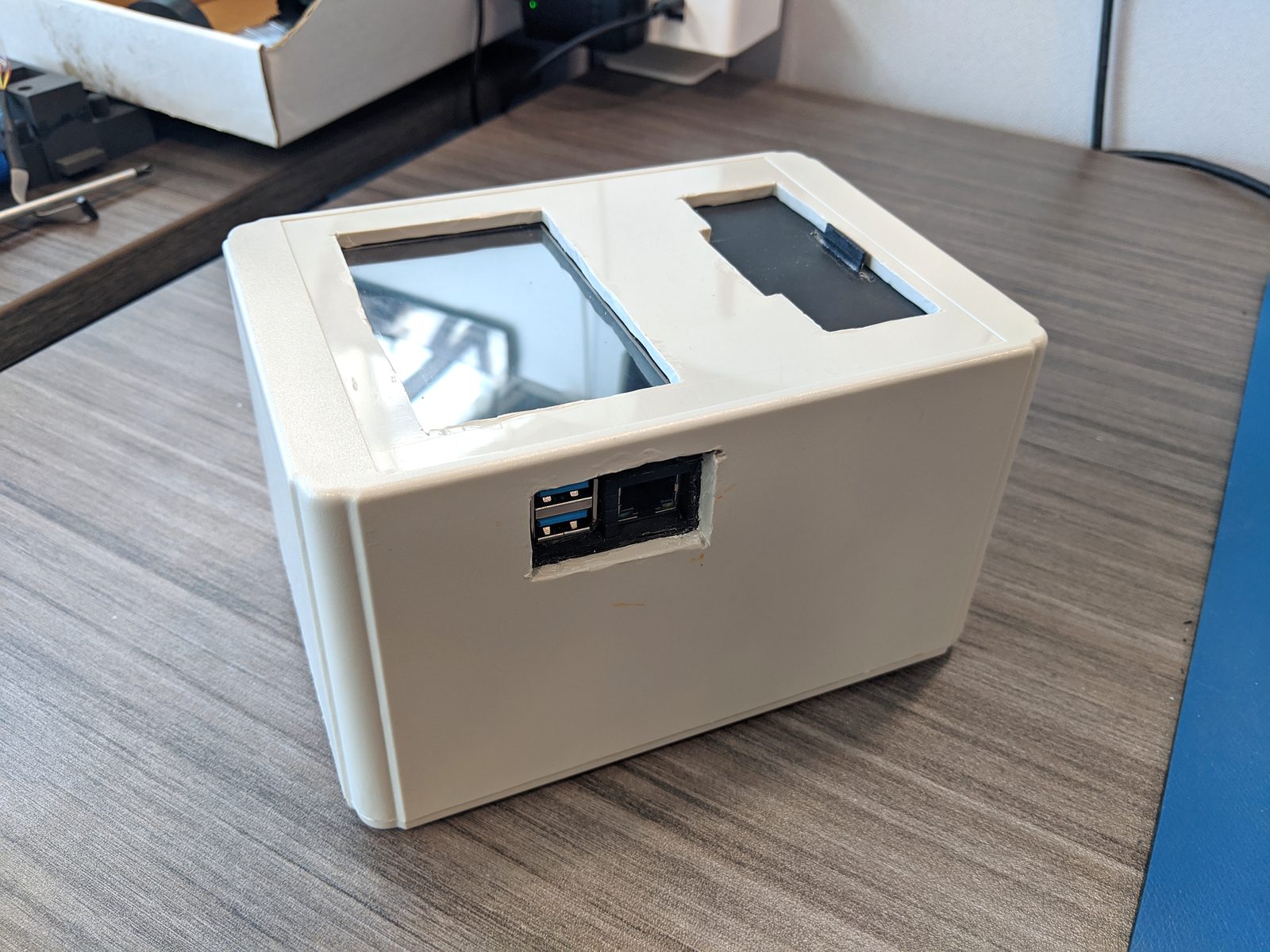
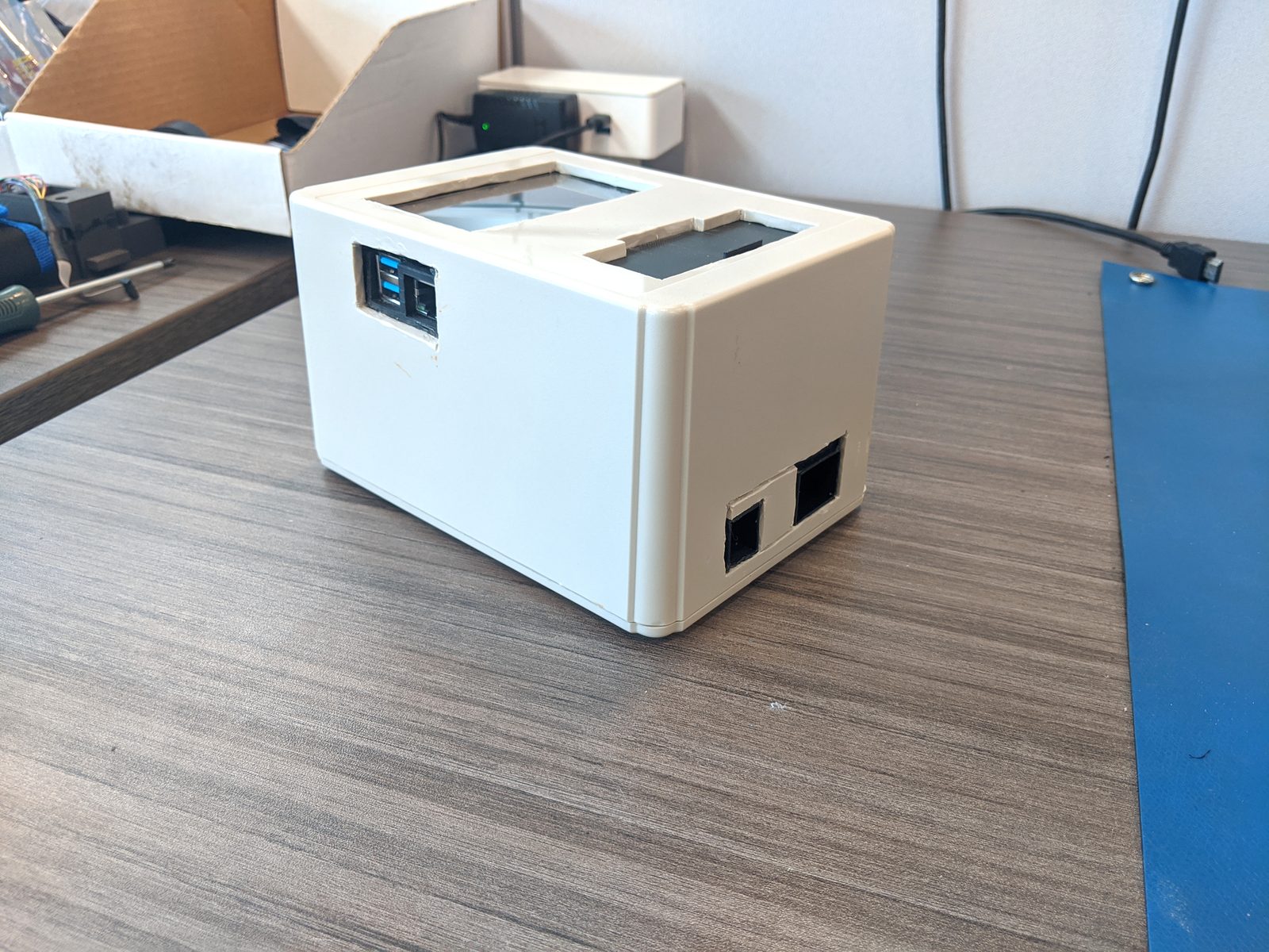
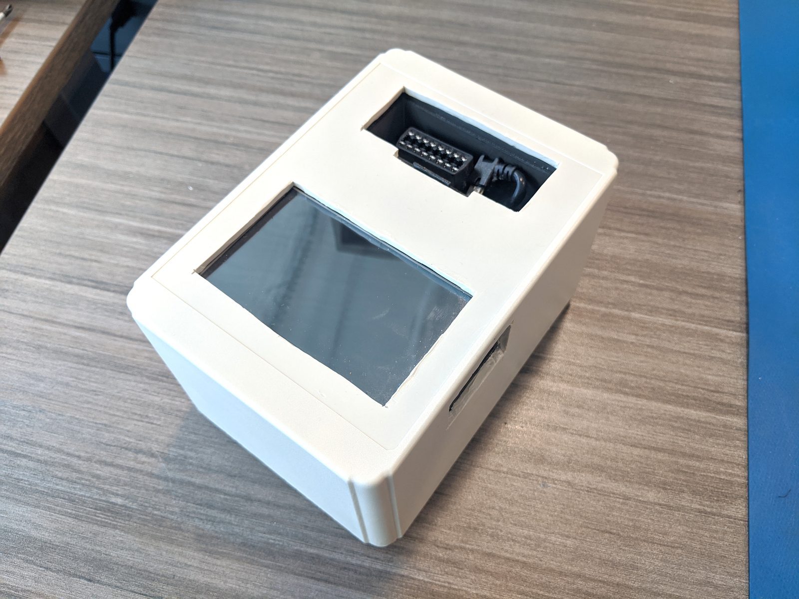
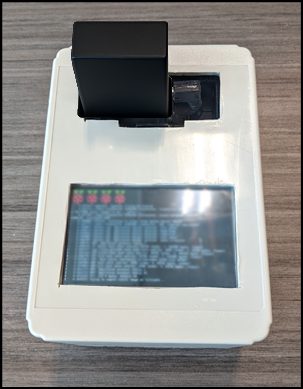
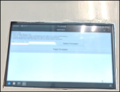
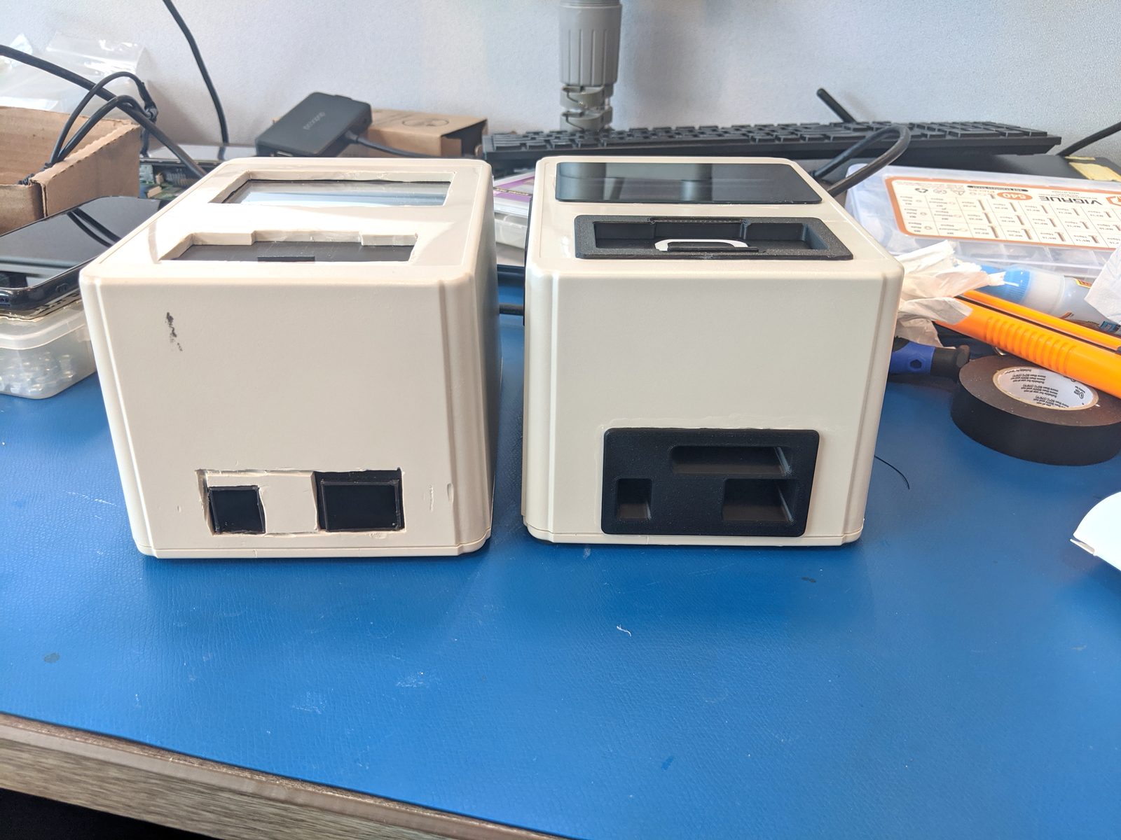
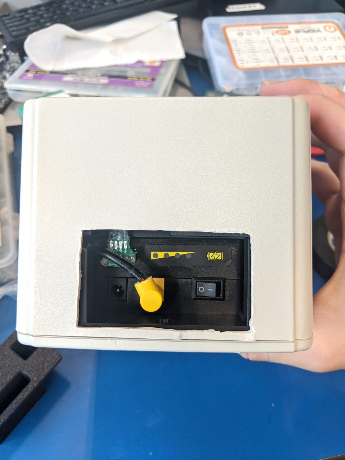
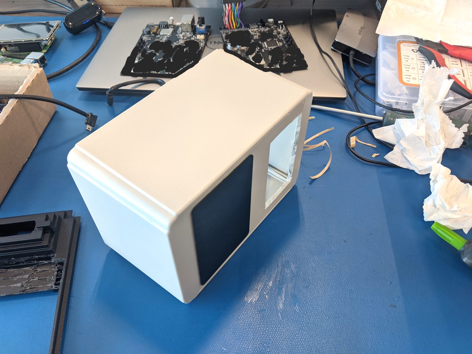
02.4 Prototype V1 Iteration & Tkinter Software Bring-Up
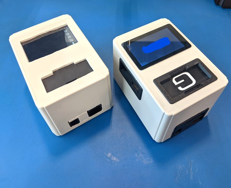
Initial operational V1 unit with Raspberry Pi 4 running Ubuntu, Tkinter GUI, and Dremeled enclosure ports for functional proof-of-concept.
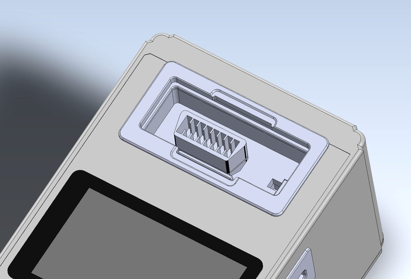
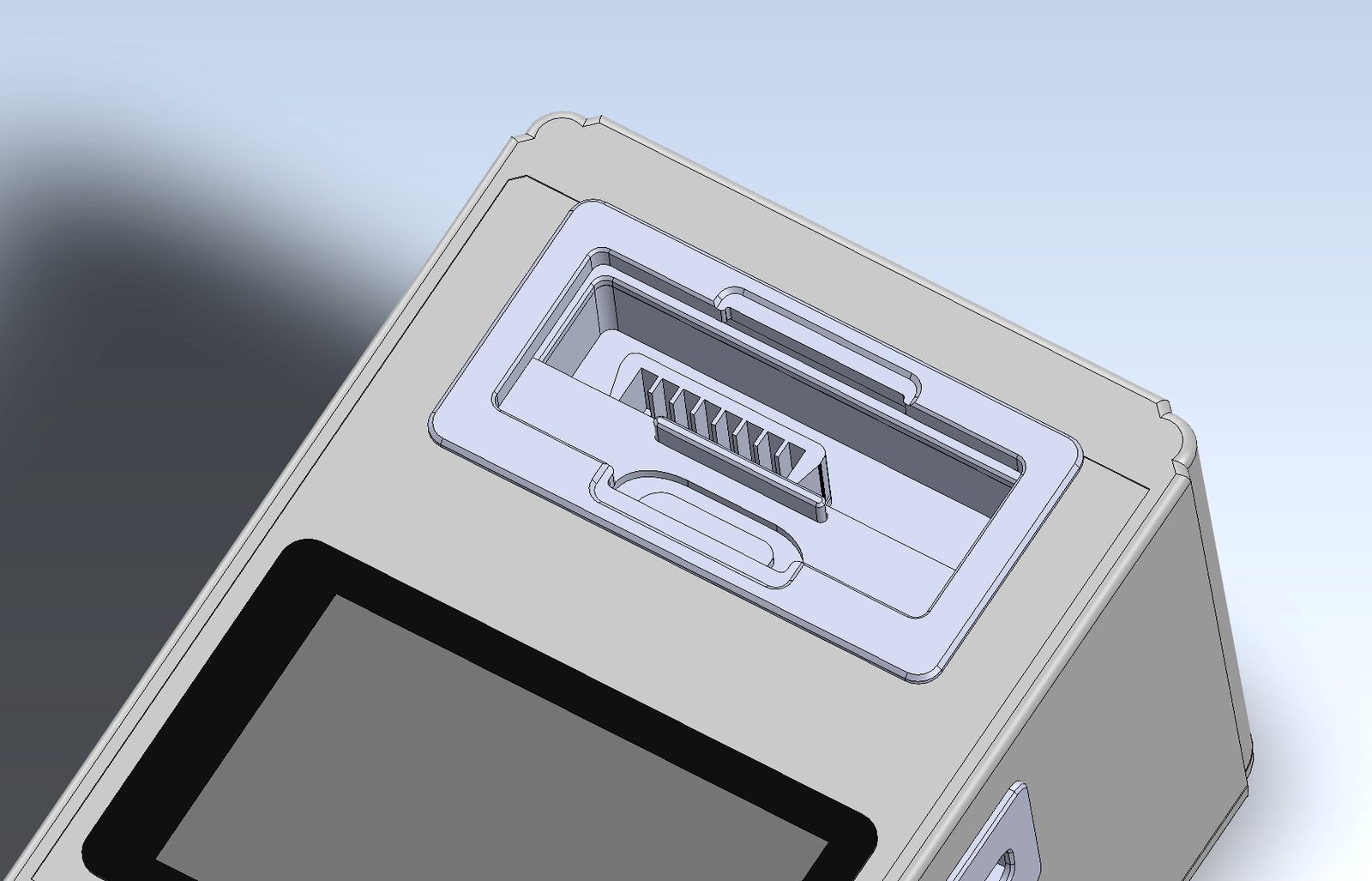
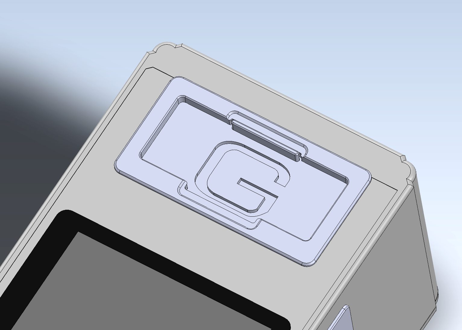
02.5 Sliding Harness Door & Port Cover Track
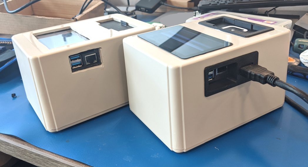
Upgrading from rough Dremel cutouts to smooth injection-quality sliding doors with detents for cable harness mating.
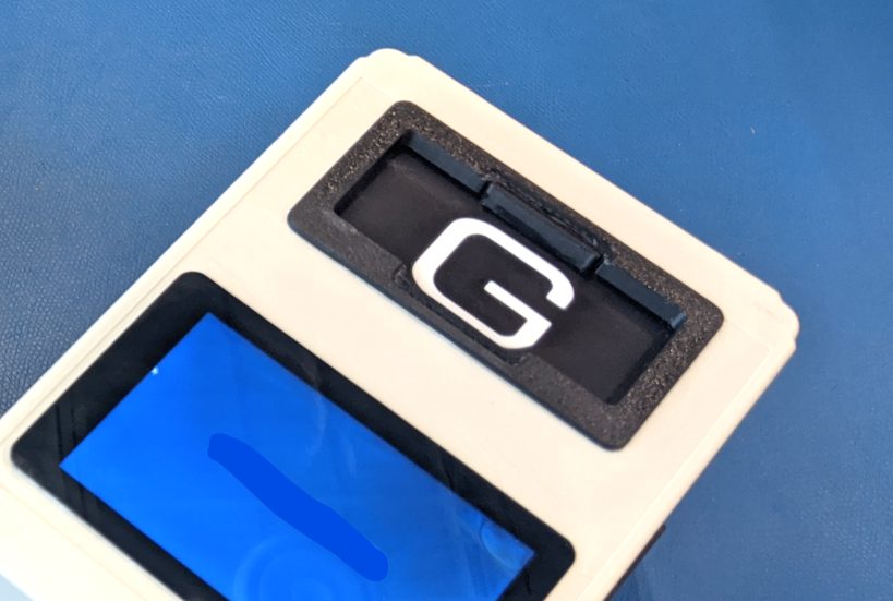
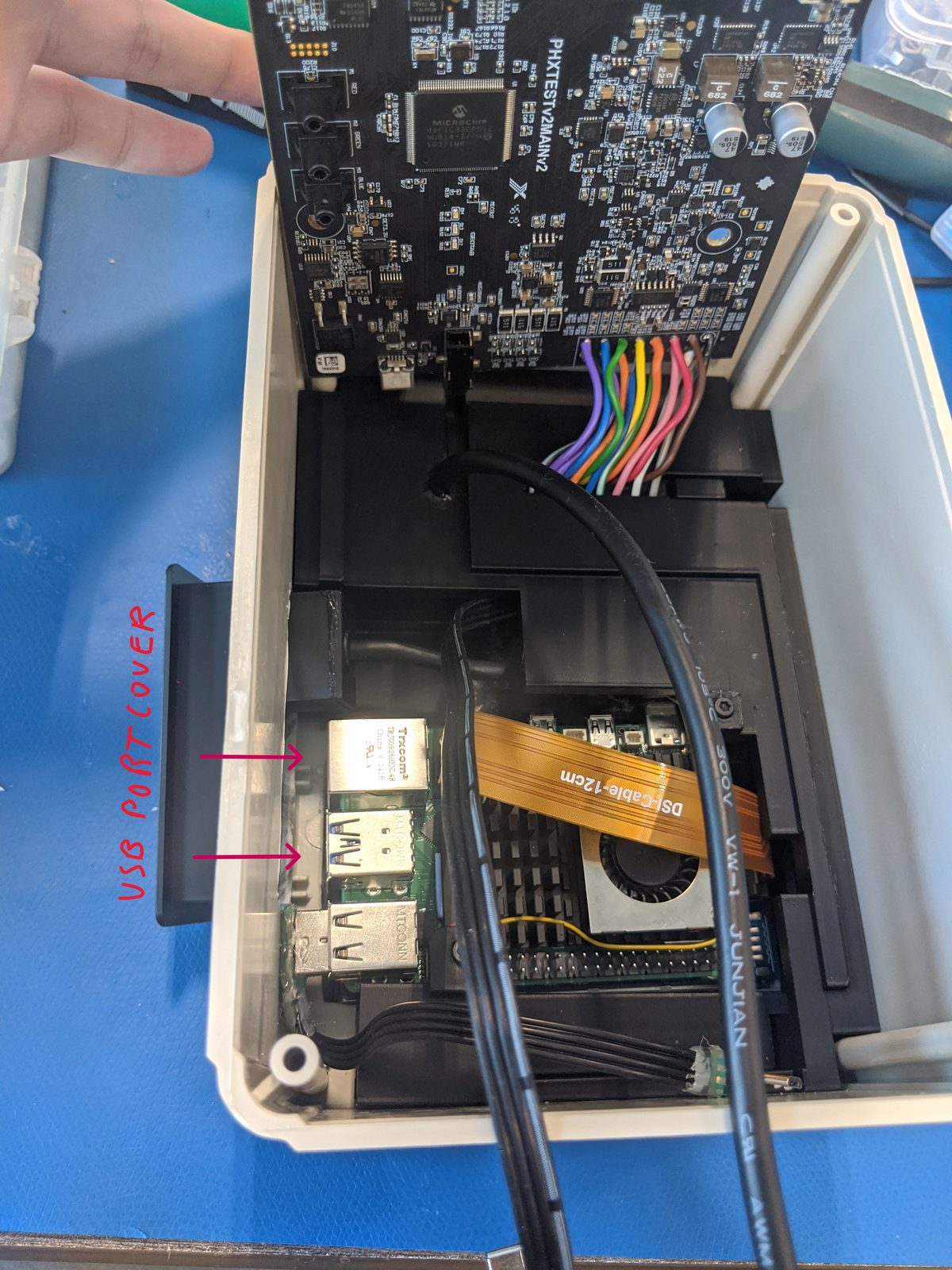
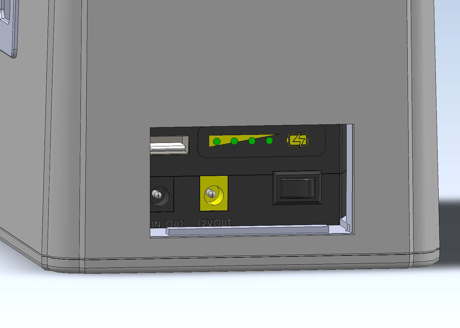
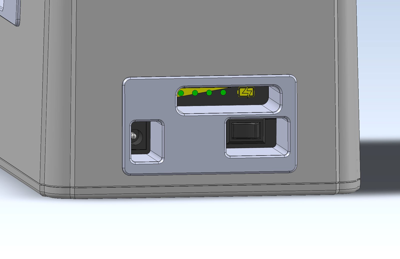
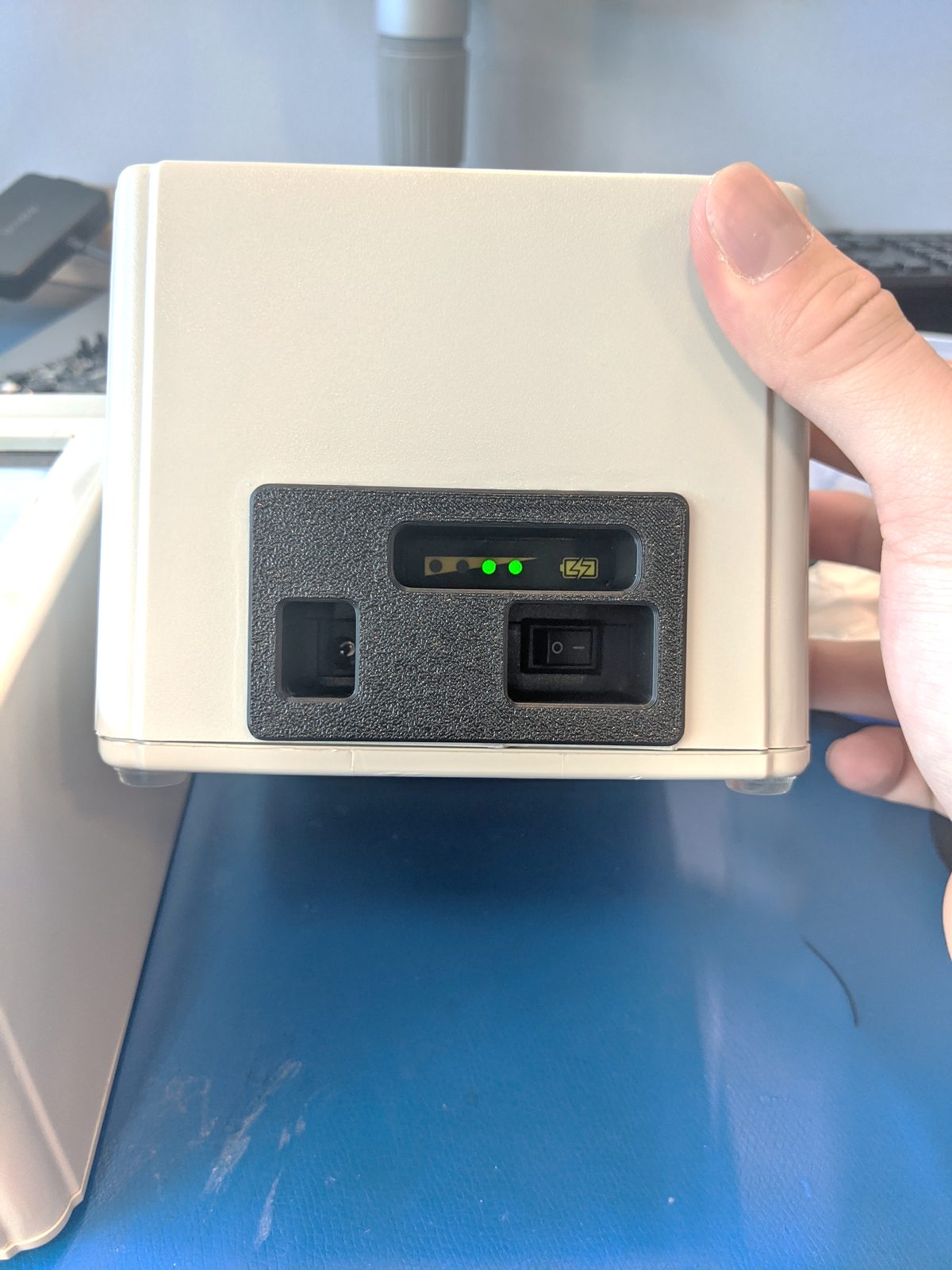
02.6 USB Port Cover & Battery Switch Bezel
Precision port covers for USB-A, USB-C, HDMI, and integrated LED battery fuel gauge windows with power toggle switch bezels.
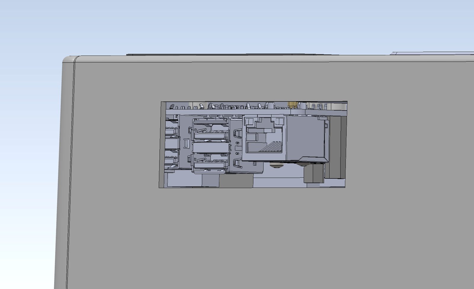
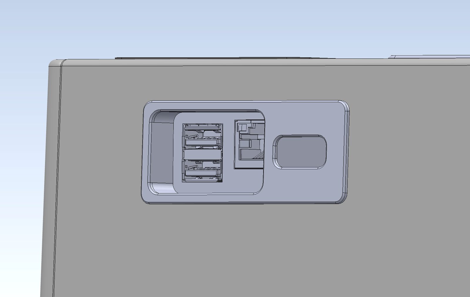
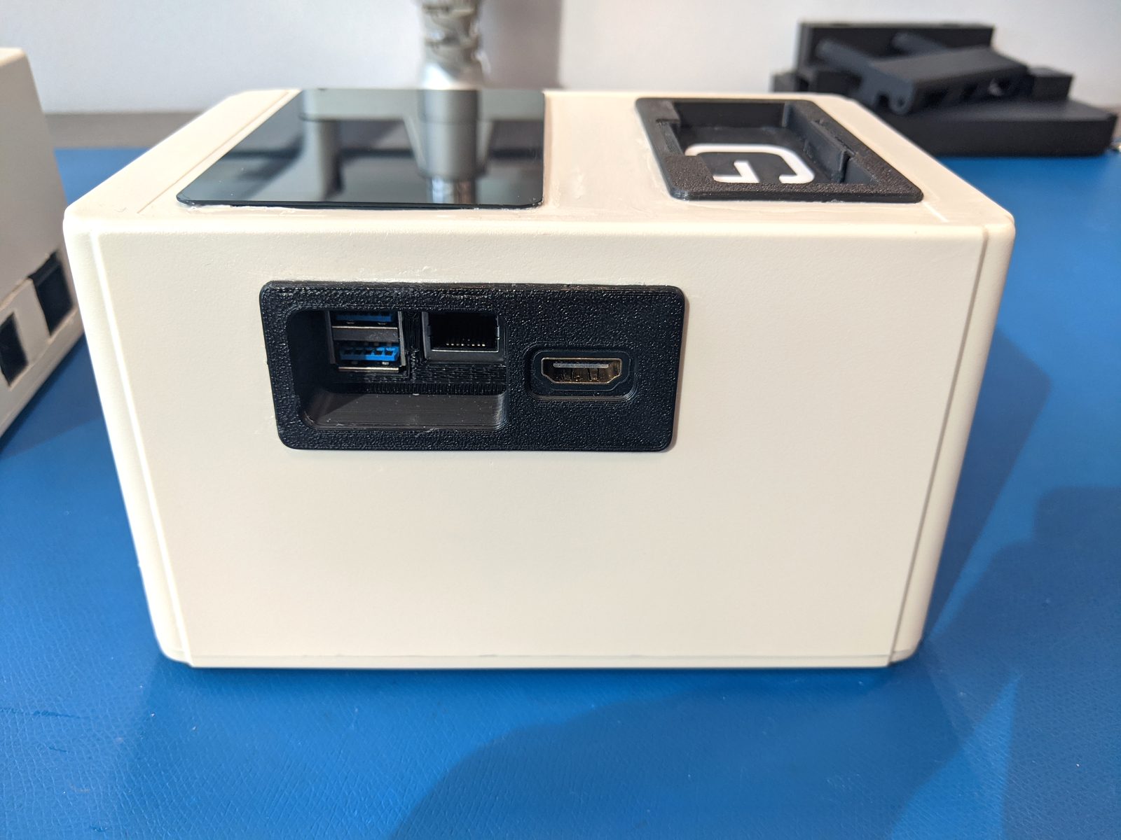
02.7 Wire Routing Channel Revisions & Clearances
Internal frame geometry modifications expanding wire path cross-sections to eliminate pinch hazards and reduce cable bend fatigue.
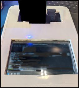
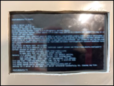
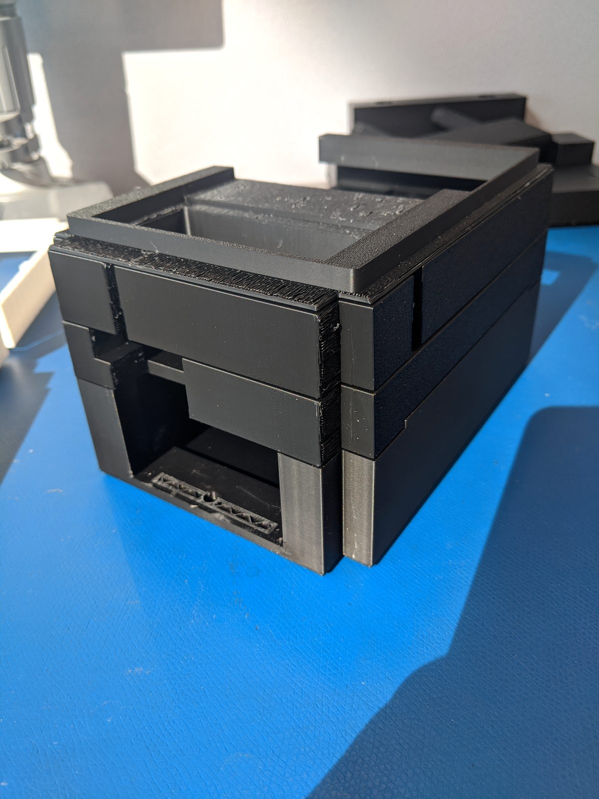
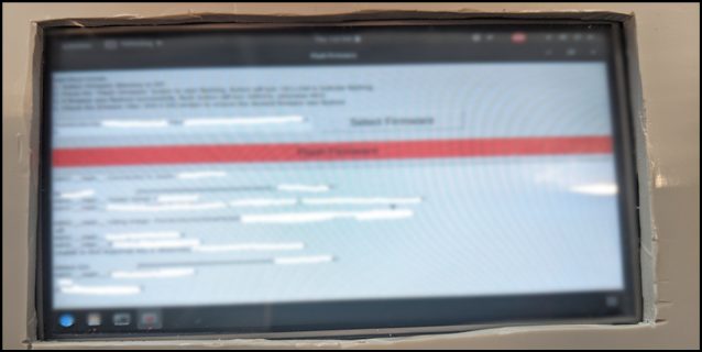
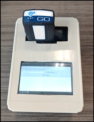
02.8 Field-Ready V2 Architecture vs. V1 Benchmark
Side-by-side comparison of the rough V1 prototype versus the sleek, industrial-grade V2 tool featuring Raspberry Pi 5 and Windows 11 compatibility.
03Electrical, Firmware & Hardware Integration
Schematic capture, PCB routing, sensor interfacing, actuator control, and embedded firmware implementation.
03.1 Inter-Layer Cable Routing & Signal Separation
Clean routing of power buses, data lines, and debug harnesses through isolated 3D printed frame channels.
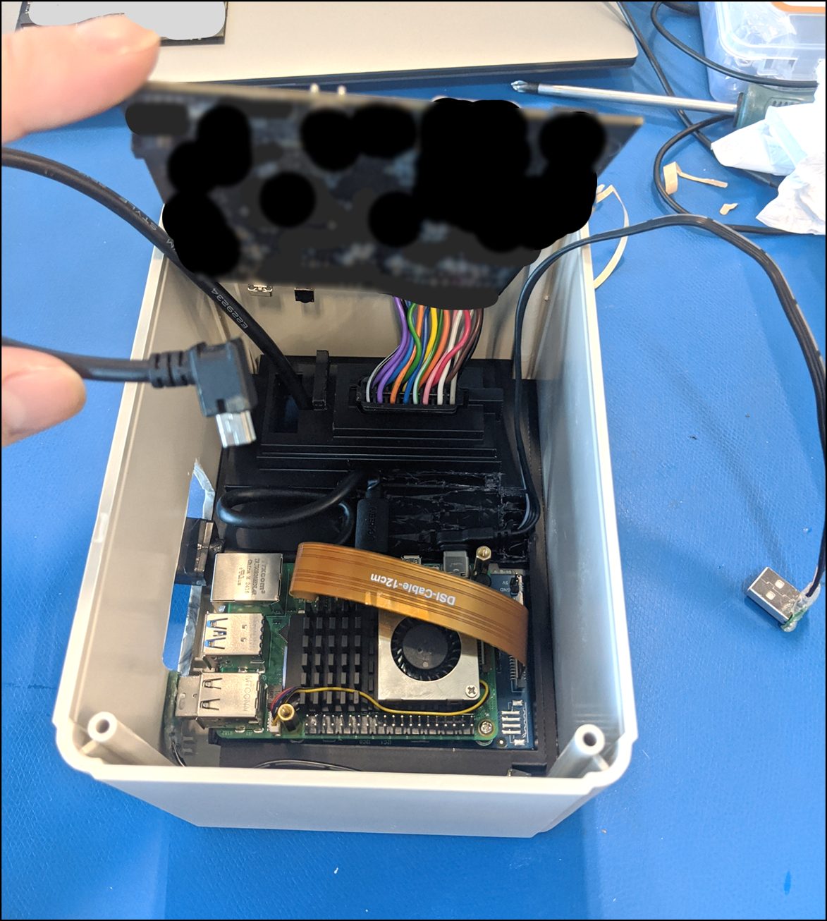
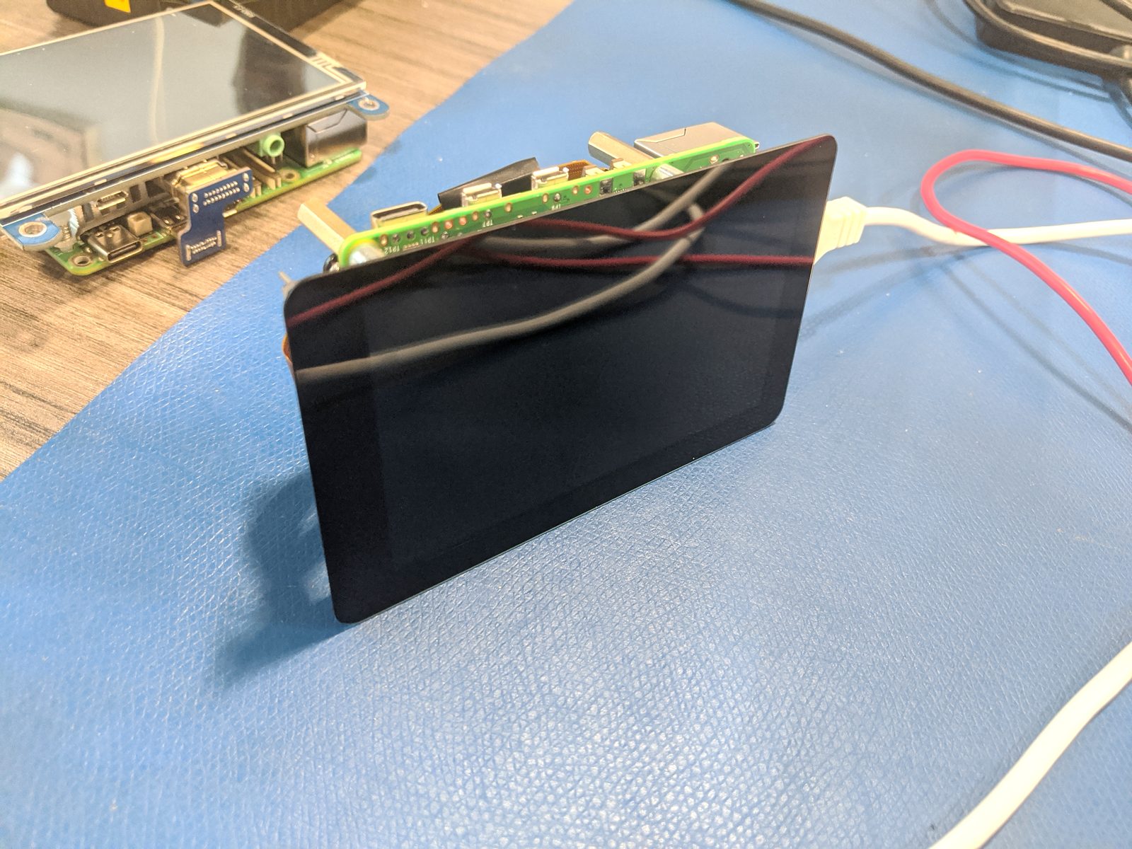
03.2 Raspberry Pi 5 & 4-Inch Touchscreen Integration
Mounting capacitive glass touchscreen and Raspberry Pi 5 compute engine with active cooling heatsink and HDMI display pass-through.
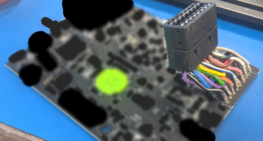
03.3 Custom Tester PCB & Direct Harness Soldering
Direct-soldered high-reliability external connector harness onto custom tester board, eliminating intermediate interconnect points.